As a fastener repair and reinforcement component embedded in base materials to form high-strength, highly wear-resistant internal threads, threaded inserts are widely used in low-strength materials such as aluminum alloys, magnesium alloys, and plastics, as well as in threaded hole repair scenarios requiring frequent disassembly. They effectively enhance thread connection strength, wear resistance, and corrosion resistance, extending the lifespan of base material threads several times over. However, the superior performance of threaded inserts relies entirely on correct, standardized installation and subsequent maintenance. Improper installation can lead to insert damage, incomplete seating, and thread misalignment, severely compromising their effectiveness. Based on years of practical experience, Shenzhen Toprecision Technology Co., Ltd. systematically outlines the complete installation, inspection, and maintenance processes for wire thread inserts and self-tapping inserts, ensuring users can fully leverage the technical value of threaded inserts.
I. Understanding and Selecting Threaded Insert Types
Before installation, the correct insert type must be selected according to application requirements.
-
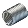
Wire Thread Insert: Made of high-strength, high-precision diamond-cross-section stainless steel or high-temperature alloy wire, available in free-state and tang-state. Mainly used for:
-
Reinforcement: Forming solid, wear-resistant standard internal threads in soft or low-strength materials like aluminum, magnesium, copper, and plastics.
-
Repair: Restoring worn or damaged original internal threads to their original specifications.
-
Anti-loosening: Its elastic structure effectively compensates for gaps, absorbs vibrations, and prevents thread loosening.
-
Conversion: Converting between imperial and metric threads.
-
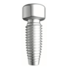
Self-Tapping Insert: Typically made of stainless steel, featuring cutting or forming blades on its external threads. It requires no pre-tapping; it self-taps or extrudes matching threads into the base material during installation. Mainly used for:
-
Non-metals and thin plates: Rapidly forming high-strength threads in plastics, wood, composites, and thin-walled metal parts.
-
Blind hole applications: Particularly suitable for blind holes with closed bottoms.
-
Mass production: Offers fast installation speed and high efficiency.
II. Key Preparations Before Installation
"A craftsman must sharpen his tools before perfecting his work." Adequate preparation is half the battle for successful installation.
-
Pilot Hole Machining: This is the most critical step. The pilot hole must be machined precisely according to the specification table provided by the manufacturer.
-
Diameter: Strict requirements apply to the pilot hole diameter. Too small causes installation difficulties or insert damage; too large results in poor embedment and reduced torque.
-
Depth: The pilot hole depth must ensure that, after installation, the insert's end face is 1-1.5 pitches below the base surface, with sufficient clearance at the bottom (especially for tang-type wire thread inserts).
-
Precision: The hole wall should be smooth, vertical, and free of burrs or taper. Special stepped drills or reamers are recommended.
-
Cleaning: Before installation, chips, oil, and impurities inside the pilot hole must be thoroughly removed using compressed air, a vacuum cleaner, or cleaning agents. Any residue will affect installation accuracy and ultimate load-bearing capacity.
-
Tool Preparation:
-
Wire Thread Inserts: Require special installation tools, including an installation mandrel and a sleeve handle. The front thread and guide slot of the mandrel must precisely match the insert specification and be free of wear.
-
Self-Tapping Inserts: Standard hex wrenches or electric/pneumatic screwdrivers with special drivers (matching the insert's hex or Torx socket) can usually be used.
III. Standard Installation Process and Tips for Wire Thread Inserts
-
Installation Steps:
a. Screwing In: Gently place the wire thread insert onto the guiding thread at the front of the installation mandrel, ensuring the insert's tang is embedded in the mandrel's guide slot. Then, manually and smoothly screw the insert into the pilot hole vertically until the insert's end face is below the workpiece surface. Avoid using power tools during the initial stage to prevent thread skipping.
b. Tang Removal: Once the insert is properly seated, use a special break-off tool or small needle-nose pliers to apply steady upward or lateral force at the preset notch of the tang to break it off and remove it. The tang's sole purpose is to transmit torque during installation and must be removed afterward.
-
Key Tips and Precautions:
-
Alignment: Ensure the starting end of the insert is perfectly aligned with the pilot hole to prevent cross-threading caused by angled entry.
-
Feel: Resistance during screwing should be uniform. If resistance suddenly increases, stop immediately to check for debris or pilot hole sizing issues; do not force it.
-
Depth Control: Installation tools with limiters or scale marks on the mandrel can be used to control depth. The top of the insert should be below the surface but not too deep.
IV. Key Points for Self-Tapping Insert Installation
-
Mount the self-tapping insert onto the matching driver.
-
Align vertically with the pilot hole, apply appropriate axial pressure, and start the tool at a low speed. For cutting-type self-tapping inserts, the process is similar to tapping and produces chips; chip evacuation must be noted.
-
Stop screwing when the insert's end face is flush with the workpiece surface or reaches the predetermined torque (some inserts are designed with torque-prevail features).
-
After installation, it is recommended to test-thread with a matching bolt to remove any minor burrs or chips.
V. Installation Quality Inspection
Post-installation inspection is mandatory.
-
Visual Inspection: The insert should be installed straight, without top protrusion or obvious tilting. For wire thread inserts, the tang must be completely removed with a flat fracture surface.
-
Go/No-Go Gauge Check: Use a thread plug gauge of matching precision to inspect the internal thread of the insert. The "Go" gauge should screw in smoothly through the entire effective length, while the "No-Go" gauge should not screw in more than 2 turns. This is the most direct method to verify thread precision.
-
Pre-torque Test (Optional): For critical locations, a torque wrench and standard bolt can be used to test-thread, checking for smooth torque and recording the value as a baseline reference.
VI. Common Fault Diagnosis and Troubleshooting
-
Thread skipping or incomplete seating: Usually caused by an oversized pilot hole, tilted installation, worn tool guide, or overly fast starting speed. Check and correct the pilot hole, replace tools, and slow down the initial installation speed.
-
Insert distortion or thread damage: Caused by an undersized pilot hole, burrs, or forced installation. Correct the pilot hole and clean burrs.
-
Tang difficult to break or uneven fracture: Mismatched break-off tool, misalignment with the notch, or improper insert material/heat treatment. Use the correct tool and apply steady force aligned with the notch.
-
Bolt cannot be screwed in or abnormal tightening torque: Possibly due to damaged internal threads during installation, residual tang fragments, or uncleared chips. Use a thread chaser (commonly known as an insert comb) to repair and thoroughly clean the hole.
VII. Maintenance and Removal/Replacement During Use
-
Routine Maintenance: Regularly inspect threaded connections for looseness or corrosion. When removing bolts, use compliant tools to avoid brutal operations that damage the insert's internal threads.
-
Removal: To remove a wire thread insert, use a special removal tool; its inverted taper blade hooks the bottom of the insert to extract it via reverse rotation. Self-tapping inserts can usually be unscrewed in reverse.
-
Replacement: After removing the old insert, use a tap (typically one size larger than the original pilot hole tap) to clean the base thread, or re-machine to the standard pilot hole size before installing a new insert.
Conclusion





















 Login
Login








 Contact
 WeChat
 粤ICP备2025493240号-1