Technical drawings of fasteners accurately convey design intentions and serve as the sole technical basis for manufacturing, inspection and procurement. The ability to read drawings accurately and efficiently directly determines the correctness of production and assembly, as well as the final product quality. Mastering the technical “language” of fastener drawings is a core competency for engineers, quality personnel, procurement specialists and production technicians. This article systematically introduces the methods and key points of reading and understanding fastener technical drawings from the perspectives of drawing composition, symbol definition, tolerance interpretation and technical specifications.
I. Basic Composition of Technical Drawings: Beyond Orthographic Views
A complete fastener working drawing consists of the following core elements:
1. Title Block
Located at the bottom right of the drawing, the title block contains administrative information including part name, drawing number, material, weight, scale, designer, approval records and company information. The drawing number acts as the unique identification code of each part.
2. Graphic Representation
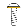
Main views, sectional views and partial enlarged views are adopted to fully display fastener structures. For bolts and screws, full or half sections are commonly used in main views to present detailed features such as head structure, shank profile, thread runout and guide end. Multiple views are applied for complex special-shaped fasteners to eliminate ambiguous structural information.
3. Dimensions and Tolerances
As the core of technical drawings, dimensional information includes the following categories:
Nominal Dimensions: Standard structural dimensions such as thread specification M10 and overall length L=40mm.
Limit Dimension Tolerances: Allowable deviation values for shank diameter, head size, across-flat width and across-corner dimensions. For example, 14h13 indicates an across-flat width of 14mm with a tolerance band of h13.
Geometric Tolerances: Expressed in framed symbols, including straightness, perpendicularity, coaxiality and circular runout, which control the form and positional accuracy of fasteners. For instance, the perpendicularity requirement of the bolt head relative to the shank axis directly affects uniform wrench force distribution during assembly.
4. Surface Structural Requirements (Roughness)
Marked with standard symbols on contour lines or dimension lines, surface roughness of thread flanks, bearing surfaces and fitting shank surfaces critically influences friction coefficient, fatigue strength and anti-loosening performance of fasteners.
5. Technical Requirements
Text-based technical specifications supplement information that cannot be fully displayed graphically, covering key manufacturing and performance criteria:
Material Standards and Heat Treatment: e.g., “Material: 35CrMo in accordance with GB/T 3077”, “Quenching and tempering: 28–32HRC”, “Surface quenching hardness: 45–50HRC with a depth of 0.3–0.5mm”.
Mechanical Property Grades: e.g., “Performance Grade: 10.9”.
Surface Treatment: e.g., “Zinc plating and passivation, coating thickness: 8–12μm, 96-hour neutral salt spray test without white rust”.
Special Requirements: e.g., “Pre-applied microcapsule thread locking adhesive”, “Full-thread demagnetization”, “100% magnetic particle inspection for surface cracks”.
II. Thread Identification and Interpretation: Decoding Thread Markings
As the core feature of fasteners, thread specifications must be clearly and accurately marked on technical drawings.
1. Thread Marking Rules
Standard thread markings follow the sequence: Thread Feature Code + Dimension Code + Tolerance Band Code + Engagement Length Code + Rotation Direction.
Example: M10×1.25-6g-LH
M: Metric standard thread;
10: Nominal major diameter of 10mm;
1.25: Pitch (omitted for coarse threads; M10 defaults to a pitch of 1.5mm);
6g: Tolerance band for pitch diameter and major diameter (6 represents tolerance grade; g represents fundamental deviation). 6g is commonly used for external threads, while 6H applies to internal threads;
LH: Left-hand thread (right-hand threads are unmarked by default).
2. Thread Runout and Relief Groove
Drawings specify the length and form of thread runout, or mark “full thread” requiring complete thread machining up to the head bearing surface. Thread relief grooves are designed for scenarios where nuts need to be fully tightened to the thread root.
3. Thread Accuracy Requirements
For high-precision connections, drawings specify individual thread parameter criteria in technical clauses, such as pitch diameter roundness and cumulative pitch error, to meet high-precision assembly demands.
III. Tolerance Interpretation: Understanding Allowable Deviation Ranges
Tolerance design forms the basis for fastener interchangeability. Key interpretation rules are as follows:
1. Dimensional Tolerance
For example, Φ12±0.1 indicates the allowable diameter range is 11.9mm to 12.1mm. Hole and shaft tolerance bands must be checked simultaneously for precision fitting assembly.
2. Geometric Tolerance
Positional Tolerance: Position tolerance of Φ0.2 for bolt mounting holes controls the maximum offset from the ideal position to ensure smooth assembly.
Orientation Tolerance: Shank straightness requirements prevent bolt bending that affects installation accuracy and mechanical stress distribution.
Form Tolerance: Flatness requirements for bolt head thickness ensure uniform bearing stress.
Runout Tolerance: Comprehensive control of form and position errors, such as radial circular runout of the thread major diameter relative to the shank axis.
IV. Interpretation of Surface Treatment and Special Processes
Surface treatment specifications directly determine the corrosion resistance, appearance and friction characteristics of fasteners.
Electroplating: Clear specifications for plating type (zinc, nickel, chromium), coating thickness, post-treatment (color passivation, black passivation, sealing) and salt spray test standards.
Coating Treatment: Specifications for Dacromet coating, zinc impregnation and powder coating include coating type, thickness, curing requirements and inspection criteria.
Oxidation and Blackening: Mainly applied for basic rust prevention and appearance optimization for low-corrosion-demand scenarios.
Other Processes: Phosphating for improved lubrication and rust resistance, and wax coating for temporary surface protection.
V. Quick Reference for Professional Symbols and Marks
Proficiency in common drawing symbols is essential for efficient drawing reading:
⌀ : Diameter
⏋ : Counterbore / Countersink seat
⌴ : Arc / Spherical surface
√ with numerical value : Surface roughness Ra value
Framed box : Geometric tolerance
/` : Slope or taper
EQS : Evenly distributed
TYP : Typical feature for repeated identical structures
VI. Practical Operation and Common Error Avoidance
1. Standard Drawing Reading Sequence
Follow the fixed logic: check the title block first, analyze the structural views, interpret dimensions and tolerances in detail, and finally verify technical requirements to avoid missing key information.
2. Correlative Information Analysis
Associate dimensions, tolerances, roughness and technical specifications to accurately understand design intentions. For example, bolts requiring high fatigue strength are equipped with strict thread root roughness standards, thread rolling processes and shot peening reinforcement requirements.
3. Timely Technical Clarification
Any ambiguous, contradictory or unfeasible markings must be confirmed with designers in a timely manner instead of being processed by subjective judgment. For example, ultra-high hardness requirements may conflict with thick surface coating processes.
4. Drawing Version Management
Always apply the latest drawing version and carefully check revision marks and change descriptions to prevent quality risks caused by outdated standards.
Conclusion
Reading fastener technical drawings is a comprehensive skill that integrates standard knowledge, process understanding and spatial imagination. By mastering standard symbols and tolerance systems, thoroughly interpreting technical requirements and developing rigorous reading habits, technicians can accurately convert drawing design information into qualified finished products. As a professional precision fastener manufacturer, Yongjing Precision strictly follows customer drawing standards and provides DFM (Design for Manufacturability) analysis and optimization suggestions. The company realizes seamless docking between design and manufacturing, optimizing structural design, reducing production costs and improving product reliability on the premise of meeting performance requirements.


 Login
Login


 Contact
 WeChat
 粤ICP备2025493240号-1