Drawing Representation of Cylindrical Helical Compression Sp
[Abstract]:In mechanical manufacturing and fastener applications, springs serve as indispensable basic components due to their unique elastic properties.
I. Introduction
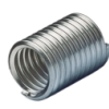
In mechanical manufacturing and fastener applications, springs serve as indispensable basic components due to their unique elastic properties. From automotive shock absorption systems and precision instrument clamping mechanisms to industrial energy storage devices and measuring tool force components, springs are ubiquitous across various industries. While spring structures vary—including cylindrical helical, conical helical, disc, and leaf springs—the cylindrical helical compression spring holds an absolute advantage in the fastener field due to its simple structure, ease of manufacturing, and stable load-bearing performance.
As the core basis for production, processing, and quality inspection, the accurate representation of cylindrical helical compression springs on drawings directly impacts product compatibility and performance stability. For professionals in the fastener industry, mastering drawing techniques and dimension calculations is key to ensuring seamless supply-demand coordination and improving production efficiency. Based on mechanical drafting standards, this article systematically outlines the drawing specifications and dimension calculation logic for cylindrical helical compression springs, helping industry personnel standardize their drawings and precisely control product parameters.
II. Drawing Specifications for Cylindrical Helical Compression Springs According to the Mechanical Drawings - Representation of Springs (GB/T 4459.4-2002), the drawing of cylindrical helical compression springs must follow simplification principles while balancing standardization and readability. The core aspects include view selection, simplified drawing methods, and detailed annotation.
(A) View Selection Cylindrical helical compression springs are typically represented using a front view combined with partial or sectional views. When the spring axis is placed horizontally, the front view should reflect core parameters such as height, pitch, and number of coils. If the axis is vertical, the front view clearly presents features like free height and compressed state. For springs with closed and ground ends, if the end structure cannot be fully shown in the main view, a partial sectional view can be added to demonstrate the perpendicularity of the ends to the axis and the ground range.
It is important to note that when a spring has many coils and does not require all of them to be drawn completely, an omitted drawing method can be used. Only 1-2 complete coils at each end are drawn, with the middle section connected by thin solid lines, while the total number of coils is clearly annotated to ensure the drawing remains both complete and concise.
(B) Key Points of Simplified Drawing
When the axis is parallel to the projection plane, the helix of the spring is simplified into straight lines in the front view; there is no need to draw the actual spiral trajectory, only using line spacing to represent the pitch. In the left (or right) view, the helix is simplified into concentric circles: the outer diameter is drawn with thick solid lines, and the inner diameter with thin solid lines. If the spring is made of solid wire, the inner diameter lines can be omitted, and only the wire diameter needs to be annotated.
Cylindrical helical compression springs with closed and ground ends are the most common type in the fastener field. The ground length of the ends must cover at least 3/4 of the wire diameter. The drawing must show the ground ends as flat planes perpendicular to the spring axis. If the ground portion is not visible in the front view, it can be shown in a partial view or directly specified in the dimension annotations.
When drawing the spring assembled with other parts, a more simplified method can be adopted by drawing only its outline (outer diameter and height) and omitting internal structures to avoid cluttered lines and highlight assembly relationships. If it is necessary to show the clearance between the spring and the part, it can be supplemented in a partial sectional view.
(C) Annotation Rules The annotation of cylindrical helical compression spring drawings must be clear and complete. Core parameters include: wire diameter ( d ), spring outer diameter ( D ), spring inner diameter ( D1 ), spring mean diameter ( D2 , where D2=(D+D1)/2 ), free height ( H0 ), working height ( H ), pitch ( t ), total number of coils ( n ), number of active coils ( n1 ), and direction of winding (left-hand or right-hand; right-hand is default and can be omitted).
Annotation principles include: dimensions should be placed close to the corresponding structures to avoid crossing and confusion; the winding direction can be noted as "LH" or "RH" above the front view; coil counts must clearly distinguish between total and active coils, as active coils directly affect elastic performance and must be precisely annotated. For standard model springs, the standard number and model can be annotated in the upper right corner of the drawing to supplement key parameters and simplify the content.
III. Dimension Calculation Methods The dimension calculation of cylindrical helical compression springs must combine usage scenarios, elastic requirements, and manufacturing processes. The calculation logic for core dimensions is as follows, providing precise parameter bases for drawing.
(A) Core Dimension Calculations
Wire Diameter ( d ): Determined based on the spring's load capacity, working stress, and material properties. The calculation formula is d=8FD2/(π[τ]n1) , where F is the working load, D2 is the mean diameter, [τ] is the allowable shear stress of the wire material, and n1 is the number of active coils. Common spring wire materials include 65Mn and carbon spring steel; allowable shear stresses for different materials should be selected according to relevant standards.
Spring Mean Diameter ( D2 ): Determined based on assembly space and wire diameter. It is usually initially set according to equipment installation dimensions and then adjusted through strength verification. The ratio of mean diameter to wire diameter ( D2/d ) is called the spring index ( C ), generally ranging from 4 to 16. A large C value can lead to unstable loading, while a small C value increases manufacturing difficulty, so it must be chosen reasonably.
Pitch ( t ): The axial distance between adjacent coils in the free state. The calculation formula is t=d+H0/n1 (for springs with closed and ground ends), where H0 is the free height. The pitch must meet the deformation requirements during compression to prevent premature contact between adjacent coils, which would affect the elastic travel.
Free Height ( H0 ): The total height of the spring without load. For springs with closed and ground ends, H0=(n1+1.5)d (when n1≥3 ). If the number of active coils is small, adjustments must be made based on the actual grinding situation to ensure flat ends and precise height.
(B) Dimension Verification Points After calculating dimensions, strength and stiffness verifications must be conducted to ensure the spring meets working requirements. Strength verification mainly validates that the shear stress of the wire under working load does not exceed the allowable shear stress to prevent fracture. Stiffness verification calculates the spring stiffness coefficient k ( k=Gd4/(8D23n1) , where G is the shear modulus of the wire material) to ensure the spring's deformation matches the working load, meeting performance requirements for shock absorption, clamping, etc.
If the verification fails, parameters such as wire diameter, mean diameter, and coil count need to be adjusted and recalculated until requirements are met. Additionally, dimension calculations must consider manufacturing processes, accounting for wire tolerances and winding accuracy, reserving reasonable machining allowances to ensure drawing parameters are feasible for production.
IV. Common Drawing Errors and Avoidance Methods During the drawing process, some practitioners easily make mistakes such as missing annotations or non-standard drawing methods, which affect production and processing. Common errors include: failing to annotate the winding direction leading to winding errors (especially for left-hand springs); ignoring end grinding requirements resulting in uneven loading after installation; mismatched pitch, free height, and coil count causing dimensional contradictions; and failing to annotate wire diameter tolerances affecting product precision.
Avoidance methods: Before drawing, clarify the spring's working parameters and assembly requirements, list core annotation items to avoid omissions; strictly follow the GB/T 4459.4-2002 standard to standardize simplified drawings, ensuring lines and views meet requirements; conduct cross-verification after dimension calculations to check the logical relationships between pitch, free height, and coil count; and supplement key tolerances, materials, and heat treatment requirements based on fastener industry manufacturing standards to enhance the drawing's guidance.


 Login
Login


 Contact
 WeChat
 粤ICP备2025493240号-1